
x
Engineers and project owners planning a 33 kV to 400 V distribution transformer need to balance duty rating, tap range, insulation, and cost. This guide walks through sizing with three‑phase formulas, practical voltage control, and a procurement checklist to align design choices with real‑world loads and sites.
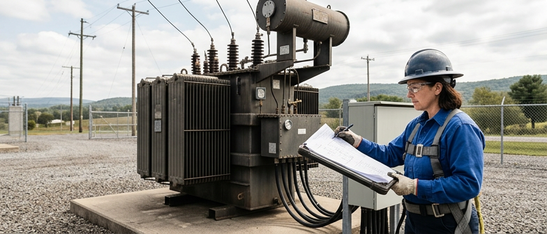
A 33 kV to 400 V transformer sits at the interface between medium voltage distribution feeders and the low voltage networks serving homes, small businesses, and light industry. In typical distribution architecture, power is transmitted at high voltage, stepped down to medium voltage at substations, and then reduced again at strategically located transformers so that end users receive safe, usable voltages. This design guide focuses on how a medium‑to‑low voltage transformer converts the incoming 33 kV into standard three‑phase low voltage suitable for downstream panelboards, protective devices, and utilization equipment, while balancing efficiency, insulation requirements, and thermal performance.
Designing for a 33 kV to 400 V step involves coordinated power and voltage reduction, insulation coordination, and attention to fault levels in modern networks. Engineers apply transformer design principles to select core materials, winding arrangements, and cooling methods that match expected load profiles and reliability needs. Understanding where these units sit in the distribution chain, and how their ratings, tap settings, and protection schemes interact with upstream and downstream equipment, allows the broader voltage transformer design guidance in this article to be applied in practical projects, from dense urban feeders to campus and industrial service entrances.
Sizing a 33 kV to 400 V transformer starts with a realistic view of the downstream three‑phase load. Engineers estimate continuous kW demand for feeders and major equipment, convert to kVA using an assumed power factor, and apply diversity factors because not all loads reach peak simultaneously. In many distribution and industrial systems, diversified maximum demand is around 60% to 80% of the simple sum. The selected transformer rating is usually set so this diversified demand remains below roughly 70% to 80% of nameplate kVA in normal operation, leaving headroom for daily variation and short‑term overloads without exceeding accepted temperature limits.
Duty rating is refined using expected load growth and operating profile. A 33 kV to 400 V transformer for a small industrial park or commercial area is commonly in the 1 MVA to 10 MVA range, while large campuses or process plants may need higher ratings. Planners forecast load over 10 to 20 years, review confirmed expansion plans, and compare installing a single larger unit with using multiple smaller transformers to provide redundancy. To optimize duty, they consider continuous base load, motor starting currents, and cyclic or emergency loading, and verify that the chosen rating and cooling method can support these conditions within the thermal limits defined by applicable standards.
Economic factors strongly influence the final rating choice. Oversizing increases purchase cost and no‑load losses, while an undersized transformer can lead to excessive voltage drop, higher stress on insulation, and the possibility of premature replacement. When estimating the cost of a 33 kV to 400 V transformer, engineers evaluate equipment price, installation and civil works, and expected lifetime losses relative to the loading pattern. Iterating between technical sizing and cost analysis helps identify a rating that operates efficiently at typical loads, maintains reasonable reserve capacity for credible future growth, and balances reliability with total ownership cost.
| Load Scenario | Typical Rating Band | Duty Characteristics | Preferred Approach | Key Trade‑offs |
|---|---|---|---|---|
| Small commercial block | Lower MVA range | Moderate diversity, limited motor starts | Single transformer | Lower cost, limited future headroom |
| Growing industrial park | Mid MVA range | Mixed continuous and cyclic duty | Slightly upsized rating | Better growth margin, higher losses at light load |
| Large process plant | Higher MVA range | High base load, frequent motor starting | Multiple transformers | Improved redundancy, more complex protection |
| Campus with phased expansion | Modular MVA blocks | Gradually increasing diversified demand | Staged installation | Aligned with load growth, repeated civil works |
| Cost‑sensitive distribution feeder | Optimized mid band | Stable load, limited overload expectation | Tight technical‑economic sizing | Balanced efficiency, constrained reserve capacity |
In a three‑phase 33 kV to 400 V transformer, rating calculations start from the required apparent power in kVA. The basic relation is S = √3 × V × I, with S in kVA, V as line‑to‑line voltage, and I as line current. Using S with the 33 kV primary voltage gives the high‑voltage current that determines winding, bushing, and protection sizing. The same kVA on the 0.4 kV side produces a higher current, guiding conductor cross‑section, busbar dimensions, and thermal limits while keeping power transfer consistent between primary and secondary.
After primary and secondary currents are obtained, the same three‑phase framework supports loss and performance checks. Copper loss is based on I²R for each winding across three phases, and core loss depends on voltage, frequency, material data, and chosen flux density. Voltage regulation is assessed by combining resistive and reactive drops using an equivalent circuit. These linked formulas help designers balance power rating, voltage steps, insulation, and cooling before detailed drawings or tests for a 33 kV to 400 V transformer.
In a 33 kV to 400 V distribution transformer, designers first define the exact primary and secondary voltages and the winding configuration. A common arrangement is 33 kV on the high‑voltage side with 400 V line‑to‑line and 230 V line‑to‑neutral on the low‑voltage side, allowing both three‑phase and single‑phase loads. Vector groups such as Dyn11 provide galvanic isolation, control phase shift, and help manage harmonic transfer. These basic choices drive the overall transformer design, including required insulation levels, clearances, and the duty ratings used in system studies.
Tap range is a central feature of practical voltage transformer design because medium‑voltage feeder levels and line drops change with operating conditions. Tap changers are usually placed on the high‑voltage winding, as off‑circuit or on‑load devices, with a typical range of about ±5 to ±10 percent around the nominal ratio. The tap schedule is selected so that the 400 V bus stays within statutory limits under varied loading and distributed generation, while remaining compatible with short‑circuit levels, thermal capability, and protection settings for every tap position.
Insulation coordination links the selected voltages and tap range to the dielectric strength of windings, bushings, and clearances. The high‑voltage side must withstand lightning impulses and switching surges at 33 kV, so insulation is graded to distribute electric stress in a controlled way. Standard basic insulation levels, coordinated with surge arresters and earthing practice, guide creepage distances, material choice, and shielding. On the low‑voltage side, requirements are lower but still aligned with prospective fault currents and transferred overvoltages, ensuring a balanced and reliable transformer design for distribution networks.
In a 33 kV to 400 V transformer, tap changers provide fine voltage control between the feeder and the low‑voltage network. Off‑load tap changers are used where primary voltage is relatively stable and adjustments are made with the transformer de‑energized. On‑load tap changers are selected when the system must keep secondary voltage within a narrow band under varying load and feeder conditions.
In typical medium‑voltage distribution designs, the high‑voltage winding tap range is limited to about ±5% to ±10%, split into discrete steps of roughly 2.5% or smaller. This range is chosen to correct normal feeder deviations without exceeding thermal or insulation limits, while avoiding unnecessary mechanical complexity, losses, and cost. Tap positions are coordinated with the expected primary voltage profile, target 400 V band, and protection settings.
A structured specification checklist is essential for any 33 kV to 400 V transformer because it links electrical performance with installation and safety constraints. Key entries include primary and secondary voltages, kVA or MVA rating, insulation and impulse levels, tap changer range, and vector group. The checklist should also cover short‑circuit strength, efficiency, temperature rise, cooling method, and site details such as ambient temperature, altitude, pollution, sound limits, and available footprint. Recording applicable standards, required tests, and documentation helps the unit meet utility and inspection requirements.
The procurement process generally starts with a technical specification and single‑line diagram, which support bid documents describing performance, delivery schedule, warranty, and factory and site testing. Prequalification of manufacturers focuses on their experience with 33 kV class transformers, standard compliance, and verified type and routine tests. During tender review, technical conformity is examined alongside commercial aspects, including delivery risk and installation and commissioning support. Before issuing a purchase order, clarifying tap changer features, accessories, protections, and switchgear interfaces reduces the chance of mismatch on site.
Cost estimation for a 33 kV to 400 V transformer depends on several technical and project factors rather than a single price figure. Core steel and conductor choices, insulation system, tap changer type and number of steps, and cooling technology affect both initial cost and long term losses. Compact layouts, low‑noise designs, or region‑specific accessories increase engineering effort. Transport, handling, and installation constraints can add significantly to overall project expenditure. When seeking quotations, providing complete technical and site information allows comparison on a total ownership basis that considers losses, maintenance, and expected service life.
What is the function of a 33 kV to 400 V transformer in distribution networks?
It steps medium‑voltage power at 33 kV down to standard three‑phase 400/230 V, allowing safe supply to households, commercial buildings, and light industry with suitable insulation and efficiency for local use.
How is the power rating and duty chosen for a 33 kV to 400 V transformer?
Engineers estimate diversified three‑phase load in kW, convert to kVA using power factor, then choose a rating so expected demand stays below about 70–80% of nameplate kVA to provide thermal margin and allow limited overload.
Which three‑phase formula is used to calculate currents for this transformer?
The standard relation is S = √3 × V × I, where S is kVA, V is line‑to‑line voltage, and I is line current. Applying the same kVA at 33 kV and 0.4 kV gives primary and secondary currents for winding, conductor, and protection design.
How do designers select tap range for voltage control on a 33 kV unit?
They define a tap range, often around ±5–10%, and use off‑load tap changers where voltage is relatively stable or on‑load tap changers if the secondary voltage must be kept within tight limits as feeder conditions vary.
What key points belong in a 33 kV to 400 V transformer specification checklist?
It should include primary and secondary voltages, kVA or MVA rating, vector group, insulation and impulse levels, tap range, short‑circuit capability, efficiency and temperature rise, cooling method, site conditions, sound limits, standards, and factory tests.